A VPW transceiver would be the ideal interface. But sadly the J1850 VPW spec is not being used in any large production products anymore. And all the transceivers are obsoleted. At least I couldn't find one for sale. Looks like we are all left with making our own interface.
In the previous post I discussed a method for receiving the VPW signal using a voltage divider and how one might go about selecting the best resistance. But there is more than one way to setp down the voltage of the VPW signal to match the Arduino. In this post I'll discuss several methods that might be used. But the voltage divider is very simple and seems to work quite well.
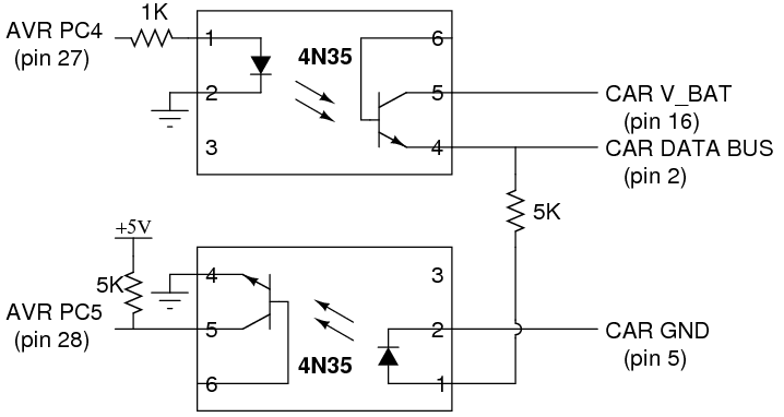
For transmitting there are also several choices. The VPW output from GM ECU was measured to be about 7.1V. to make a signal with the same voltage we will need to step up the Arduino pulse signal. But wait. As shown in the previous post the high trigger voltage spec for VPW is 4.25V. The Arduino can output this voltage. And the Arduino output is a square wave so where it is measured on the pulse won't matter. Something as simple as a diode between the Arduino output pin and the VPW line could even work. But other more sophisticated methods utilize optocouplers or MOSFET's and comparators. Like always there is more than one way to solve a problem.
But let's take a step back. When I first wanted to connect the VPW to the Arduino I didn't find many choices. One popular way was with the ELM327. I obtained an ELM327 clone and connected it to the Arduino (this video was done with an ELM327 clone between the VPW bus and the Arduino). While it did work it was limiting in many ways. I wanted a less filtered access to the bus.
More searching found this example: http://www.nerdkits.com/videos/obdii/
Their circuit uses an optocoupler for both input and and output. They reference another project which uses a voltage divider for receive and transistors for send. And the ELM327 suggested circuit also uses divider/transistor setup.
The Nerdkits also has some code posted for capturing the VPW pulses. This is more along the lines of what I was looking for. But as usual this code didn't compile on our setup and had some limitations. But it was a good starting point. We reworked the code to suit our application. More about the software later. For now back to the circuit design.
More to come on this topic Later. Out of time to type.
Did you ever make more progress? You got GitHub for any of the progress. I'm currently trying to work with gm j1850 vpw
ReplyDeleteYes we got the VPW working. I don't remember posting any code myself. But if you search for programing GM LS1 ECU's over VPW there may be some code posted that I helped on but didn't feel it was my place to post.
DeleteHi Thaniel,
DeleteAwesome work. I been reading a bunch of your posts on the E46 forum and gearheads.
Did you ever come up with an interface to go from gmlan to gm class 2?
I am looking for something to swap some things.
Many thanks
Thanks. Yes it is not too hard to interface with the GM class 2 signal. Think I wrote something on this blog about some ways to do it. GM lan is just standard CAN bus. Trick is reverse engineering all the messages. If looking for a plug and play thing you might check with pete loud160plus@gmail.com he has done a lot more with GM bus conversion. My interest at the time stopped at the ECU.
Delete